|
Polygon Mesh Processing Library
|
|
Polygon Mesh Processing Library
|
Welcome to the PMP library tutorial!
This tutorial will walk you through your first steps using PMP. After completion, you should be able to build your own mesh processing applications and use PMP for basic mesh processing tasks.
Note that this tutorial is not a comprehensive introduction to mesh processing. If that's what you are looking for, we highly recommend the textbook of Botsch et al. [3].
By the way: This is a living document that's built from the latest version of our sources. If you spot any errors, inaccuracies, or typos, please don't hesitate to report them using our issue tracker. Your feedback and suggestions are welcome!
Let's begin by getting the PMP library source code and building the library and its example applications. In the following, I'm assuming you are using a Unix-like operating system such as Linux or macOS. If you are on Windows the steps are the same but the exact commands might be slightly different.
First, clone the repository using git:
The next step is to configure the build system using CMake. Create a separate build directory for all the files you'll generate:
Now run CMake to generate the build files:
This should work out-of-the-box as long as you have recent compiler and standard build tools installed. In case of doubt, see the detailed Installation instructions.
By default, CMake will generate Makefiles on Linux and macOS. You can now build the library using
After watching a few pages of compiler output passing by, you should see something like this:
Congratulations! You successfully built PMP!
We include a number of example applications that you can to try out. The mpview application provides a simple graphical interface for many of our algorithms. You can give it a try and see what you can do with the famous Stanford bunny:
You should see a window like this:

If you're having trouble with one of the steps, please read the detailed Installation instructions carefully. You can also head over to our discussions forum and ask for help.
Polygon meshes are a fundamental data structure for representing 3D surfaces in computer graphics and geometry processing. A mesh is composed of vertices, edges, and faces:
We also call those mesh elements.
In order to access and manipulate the mesh, you also need incidence relationships between those elements. The central class for storing and manipulating all that data is pmp::SurfaceMesh. It stores connectivity information based on halfedges, i.e., pairs of directed edges with opposing direction. To be more precise:
The halfedge connectivity is illustrated in the figure below:
In the following, we show the basic usage of pmp::SurfaceMesh by example.
The basic usage of pmp::SurfaceMesh is demonstrated in the example below. The program first instantiates a pmp::SurfaceMesh object as well as four vertex handles. These handles, as well as the handles for the other mesh elements Halfedge, Edge and Face basically indices. Four vertices are added to the mesh, as well as four triangular faces composing a tetrahedron. Finally, the number of vertices, edges, and faces is printed to standard output.
In order to sequentially access mesh elements pmp::SurfaceMesh provides iterators for each element type:
Similar to iterators, pmp::SurfaceMesh also provides circulators for the ordered enumeration of all incident vertices, halfedges, or faces around a given face or vertex. The example below demonstrates the use of iterators and circulators for computing the mean valence of a mesh.
Attaching additional attributes to mesh elements is important for many applications. pmp::SurfaceMesh supports properties by means of synchronized arrays that can be (de-)allocated dynamically at run-time. Property arrays are also used internally, e.g., to store vertex coordinates. The example program below shows how to access vertex coordinates through the pre-defined point property.
The dynamic (de-)allocation of properties at run-time is managed by a set of four different functions.
Add a new property of a specific type for a given element type. Example:
Get a handle to an existing property. Example:
Get or add: Return a handle to an existing property if a property of the same type and name exists. If there is no such property, a new one is allocated and its handle is returned. Example:
Remove a property given its handle:
Functions that allocate a new property take an optional default value for the property as a second argument. Example:
The code excerpt below demonstrates how to allocate, use and remove a custom edge property.
Commonly used connectivity queries such as retrieving the next halfedge or the target vertex of an halfedge are illustrated below.
pmp::SurfaceMesh also offers higher-level topological operations, such as performing edge flips, edge splits, face splits, or halfedge collapses. The figure below illustrates some of these operations.
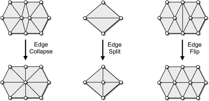
The corresponding member functions and their syntax is demonstrated in the pseudo-code below.
When elements are removed from the mesh due to topological changes, the member function pmp::SurfaceMesh::garbage_collection() has to be called in order to ensure the consistency of the data structure.
All I/O operations are handled by the pmp::read() and pmp::write() functions. They take a mesh, a file path, and optional pmp::IOFlags as an argument.
We currently support reading and writing several standard file formats: OFF, OBJ, STL. See the reference documentation for the pmp::read() and pmp::write() functions for details on which format supports reading / writing which type of data.
A simple example reading and writing a mesh is shown below.